Physical Computing

Module 1

Jasmine Rose Ramos


Module 1


Activity Research

Activity 1
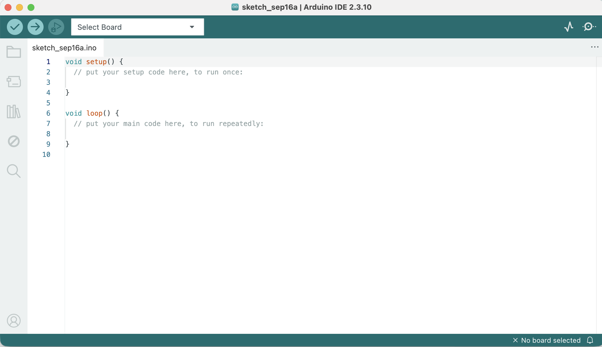
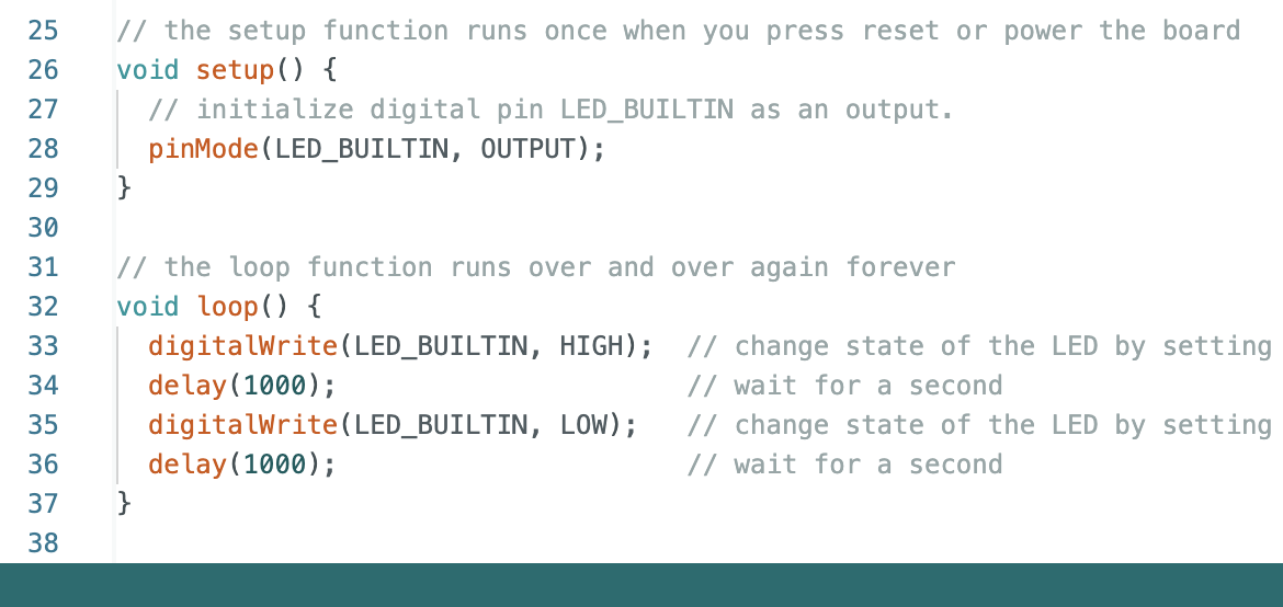
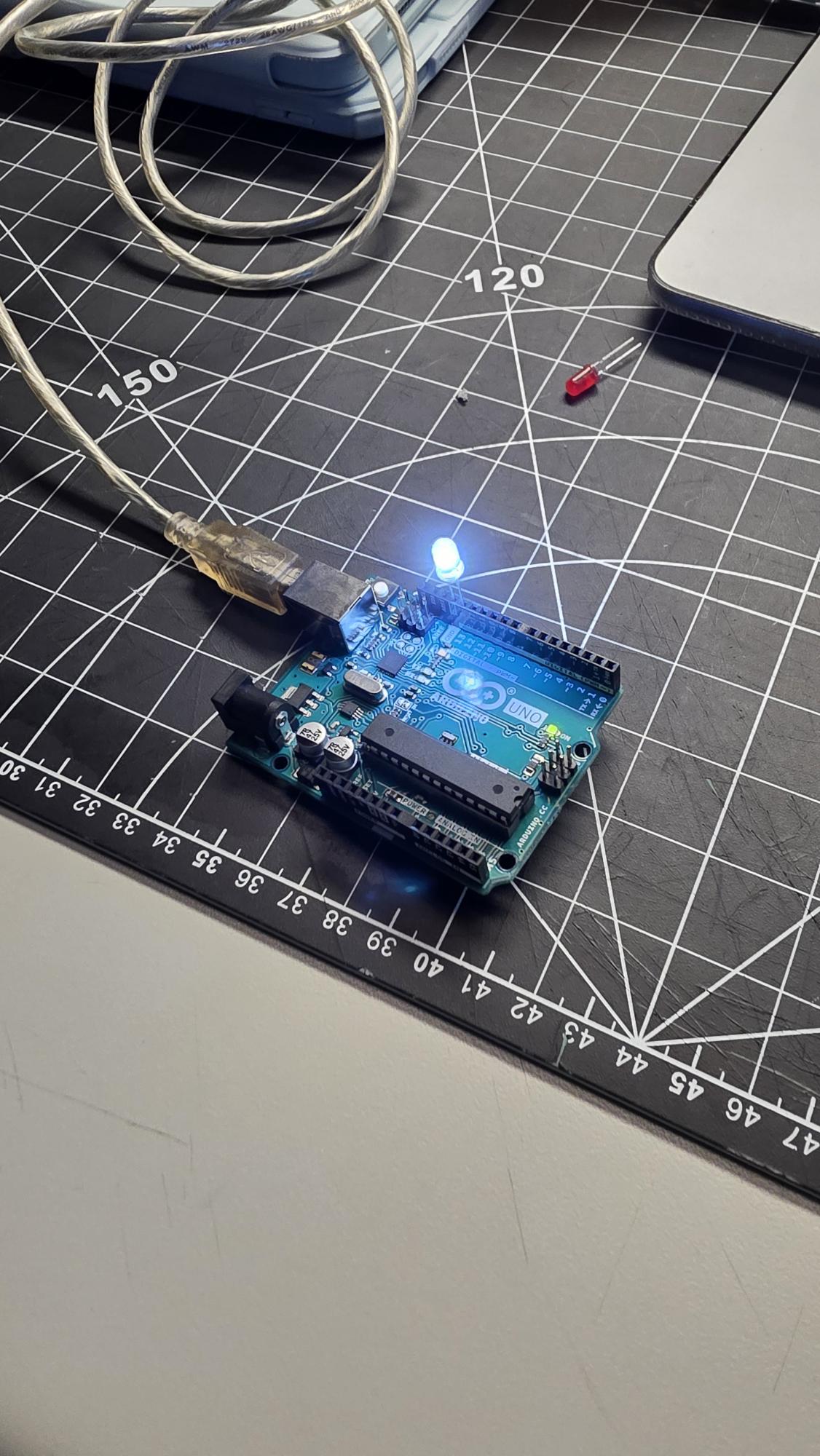
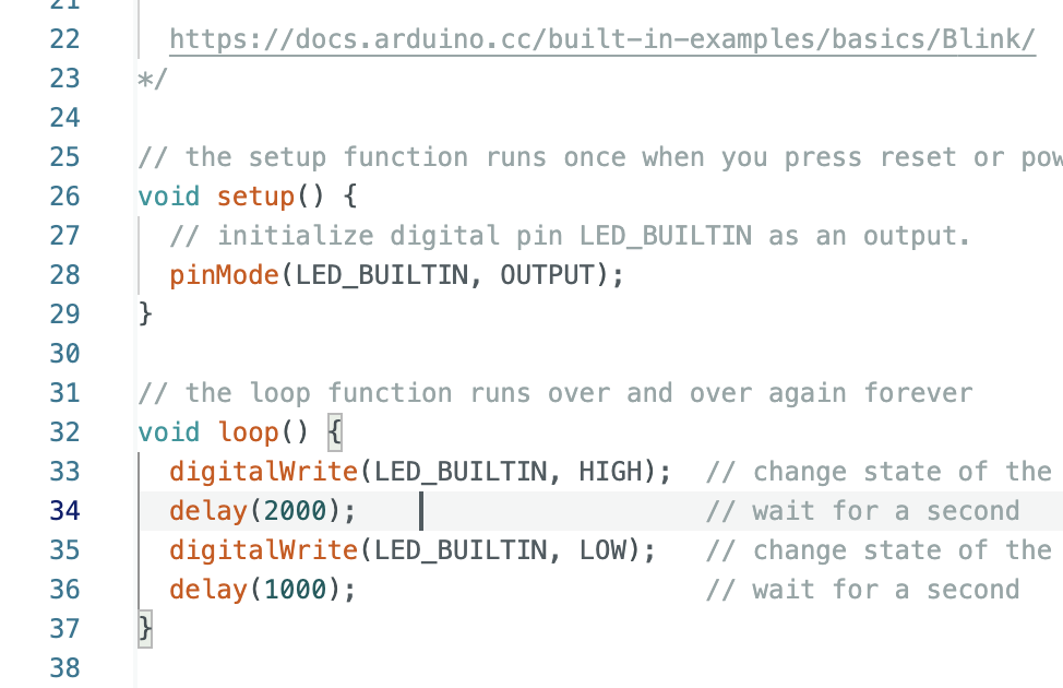
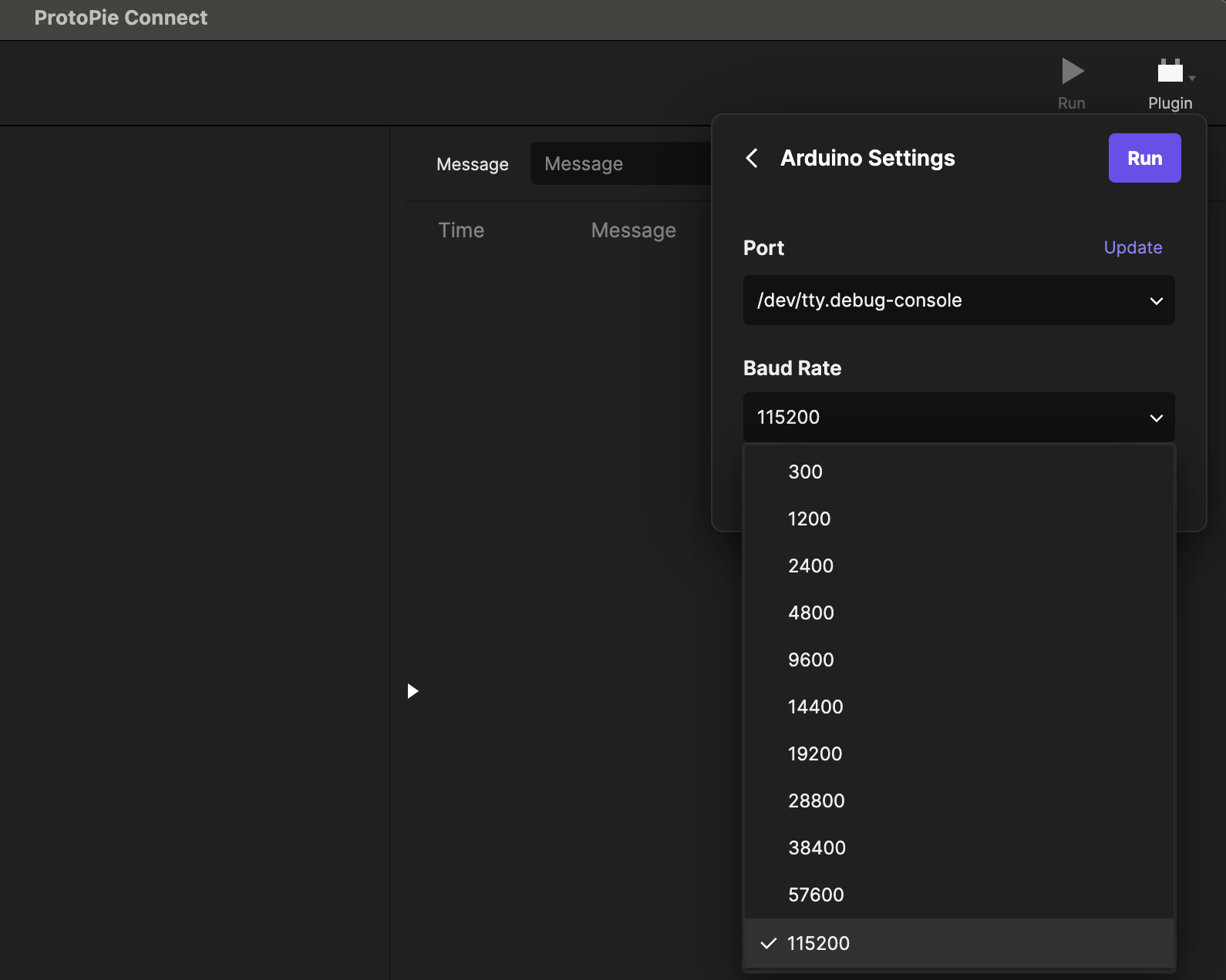
I opened the Arduino IDE (v2.3.10) to start setting up my code environment. The editor loaded a fresh sketch showing the standard setup() and loop() functions, which form the core structure for writing my microcontroller program. I wrote the initial code to make the built-in LED blink by setting LED_BUILTIN as an output in setup(). In the main loop, I used digitalWrite() commands along with delay(1000) to program the light to alternate on and off every second. I plugged my Arduino Uno board into my computer using a USB cable to power it up and run my uploaded script. Seeing the lights turn on directly on the board confirmed that my code compiled successfully and transferred to the hardware. I went back into the code to experiment with timing and adjusted how long the light stays on. By changing the high-state delay to delay(2000), I programmed the light to hold for two full seconds before turning off for one second, creating an uneven blinking pattern. I opened ProtoPie Connect to set up real-time interaction between my physical Arduino hardware and a digital interface. In the Arduino Settings window, I mapped the board's port and changed the baud rate to 115200 to ensure high-speed serial communication between both systems.

Activity 2

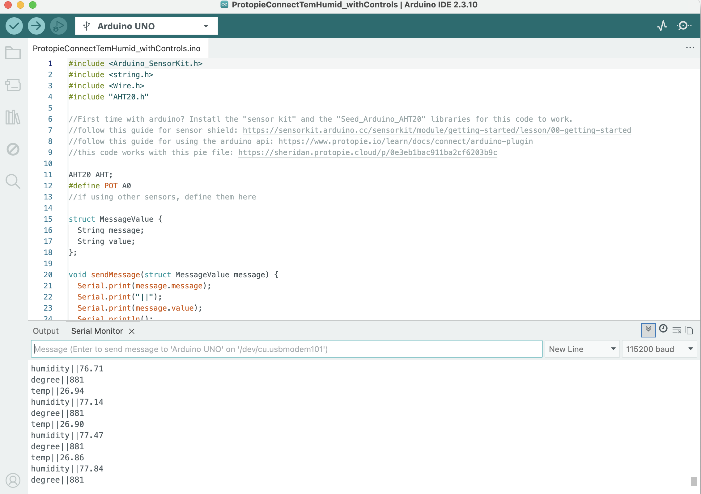
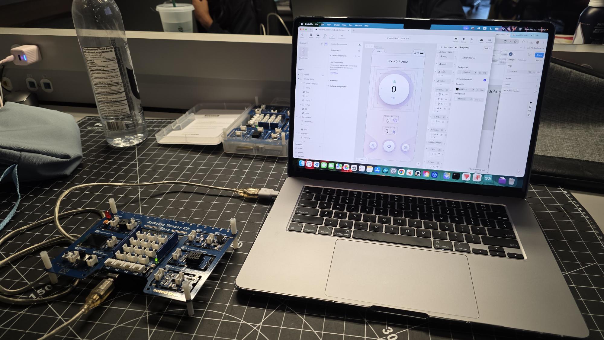
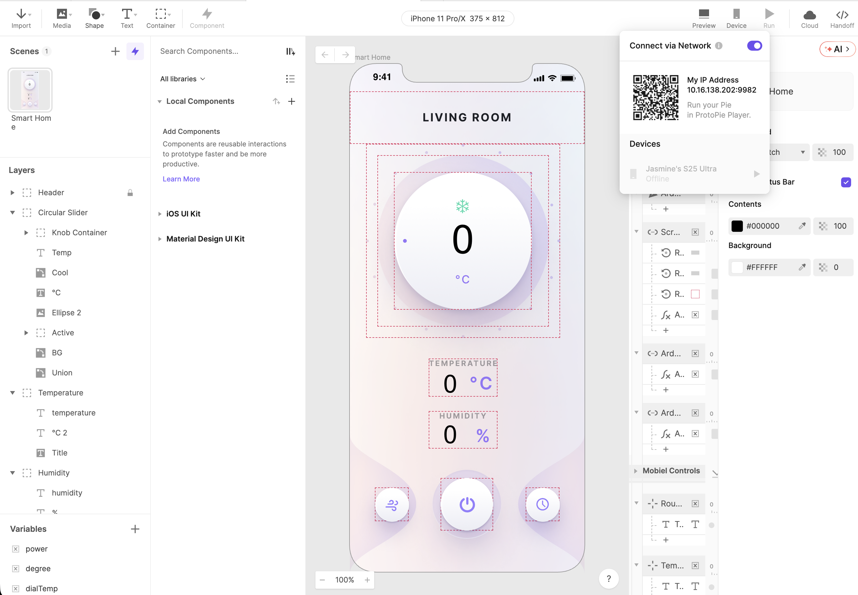
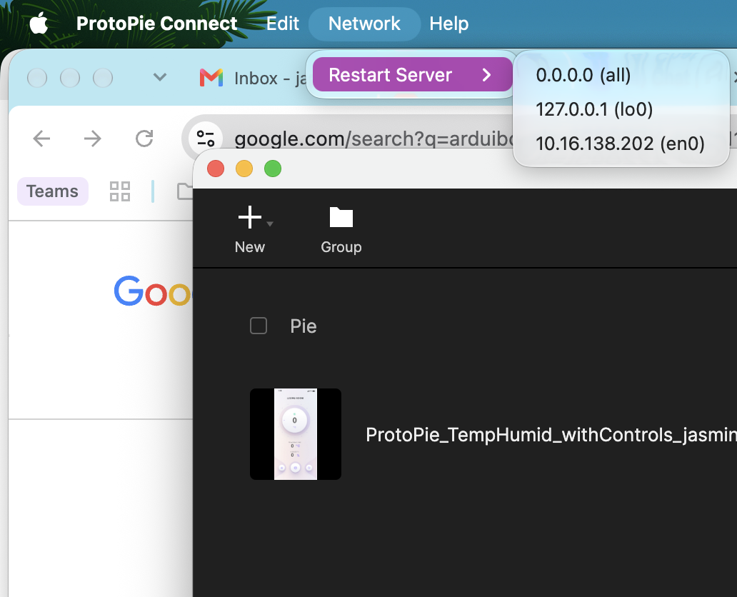
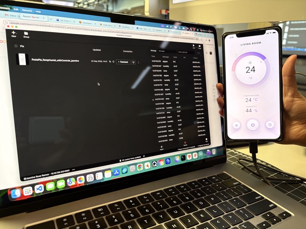
I wrote and compiled the C++ script in the Arduino IDE (v2.3.10) to read data from the environmental sensors connected to my board. Opening the Serial Monitor allowed me to inspect the real-time serial output, verifying that formatted values for temperature, humidity, and dial degree readings were broadcasting correctly at 115200 baud. I set up my physical workspace with my laptop connected directly to the Arduino Sensor Kit shield via USB. On screen, I opened my ProtoPie Studio project to start mapping the UI components to incoming sensor values from the physical board. I designed the digital thermostat UI layout in ProtoPie, featuring a prominent circular dial, numerical temperature and humidity indicators, and control toggles. I then generated a network IP connection and QR code to pair the prototype directly to a mobile testing device. I loaded the pie file ProtoPie_TempHumid_withControls_jasmine into ProtoPie Connect to handle incoming serial messages from the hardware. I checked the network settings dropdown menu to select the proper local IP address (10.16.138.202) and ensure the local server was running properly. I completed the full physical-to-digital loop by pairing my smartphone running ProtoPie Player to the ProtoPie Connect server. As I interacted with the physical sensors, the mobile app updated dynamically in real time—displaying an active room temperature reading of 24°C and a relative humidity level of 44%.

Activity 3

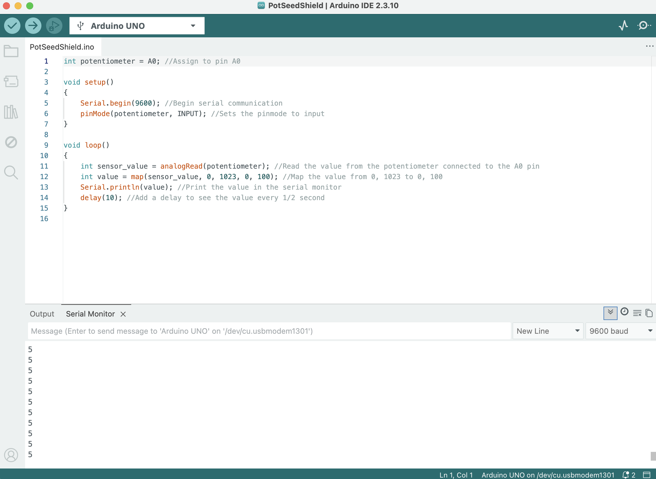
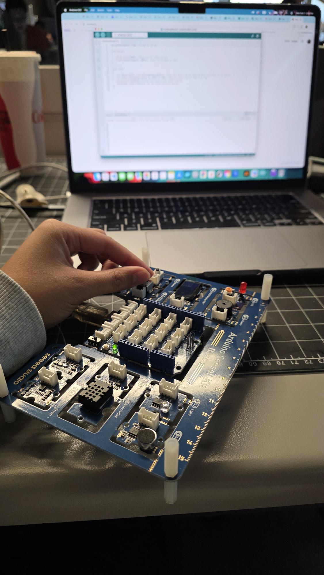
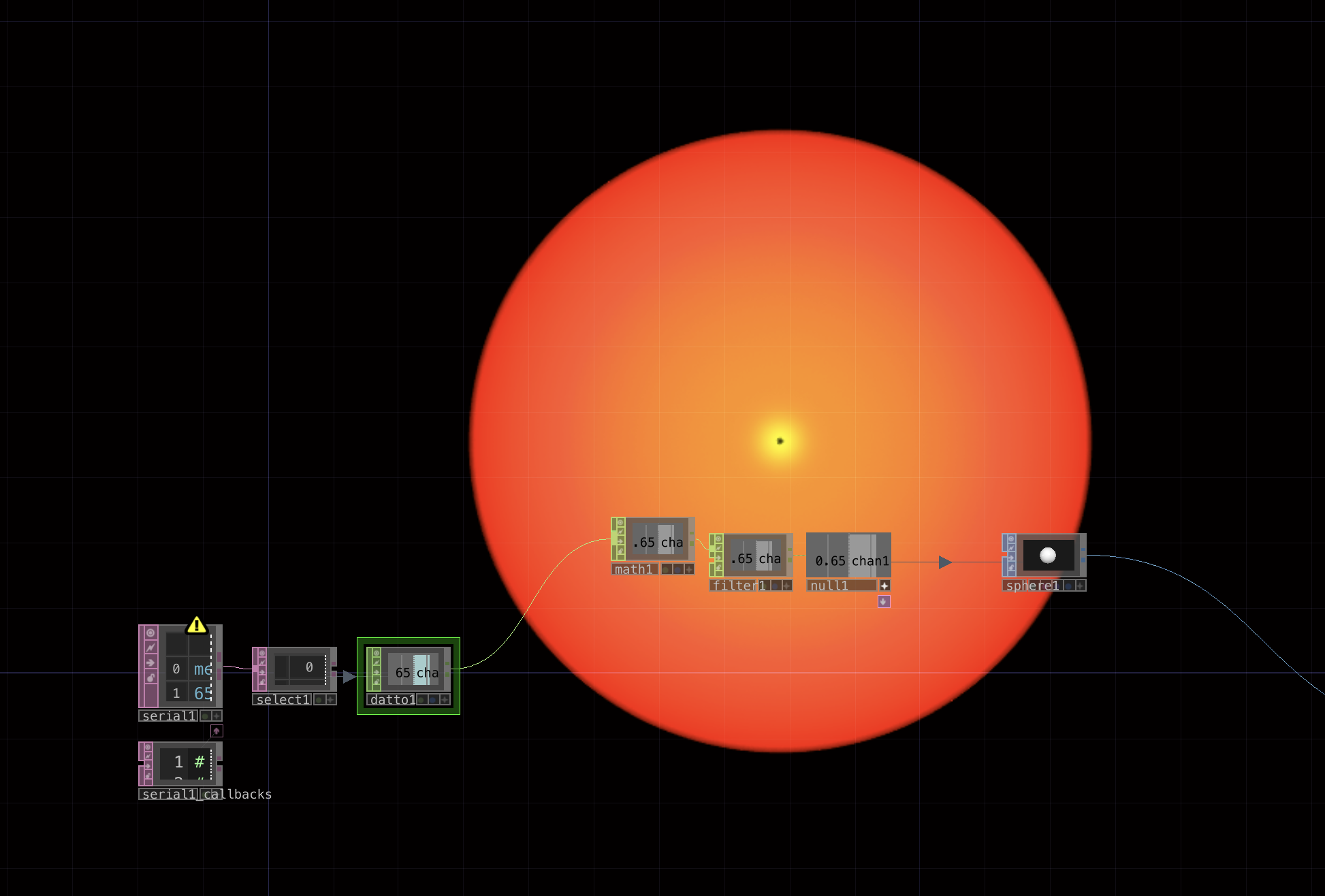
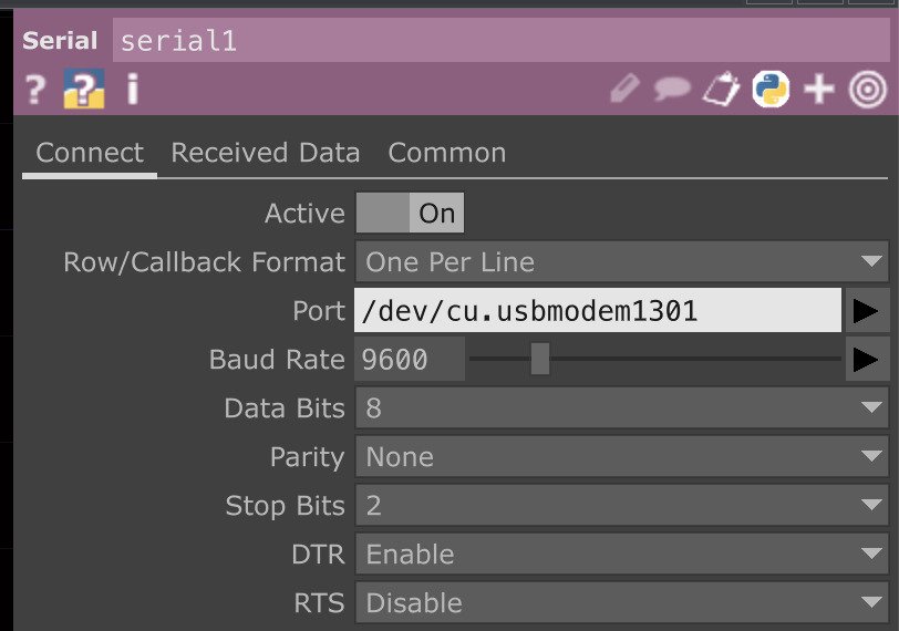
I wrote an Arduino sketch (PotSeedShield.ino) to read analog signals from a potentiometer connected to pin A0 on my Arduino Sensor Kit shield. Using analogRead() and the map() function, I scaled the raw sensor input ($0$ to $1023$) to a normalized range of $0$ to $100$ and verified the output values in the Serial Monitor operating at 9600 baud. I placed my laptop on my workstation desk with the Arduino Sensor Kit shield plugged in via USB. With the code uploaded, I manually turned the rotary potentiometer knob on the shield to generate real-time changing data inputs. The Serial Monitor displayed the corresponding mapped values, confirming that the potentiometer was functioning correctly and sending accurate readings to the Arduino board. I built a TouchDesigner node network using DATs and CHOPs,including select, datto, math, filter, and null operators, to process the incoming serial stream. I mapped the smoothed output channel to a 3D sphere SOP, controlling the size and scale of a vibrant red-orange glowing orb on screen. I configured the Serial DAT operator inside TouchDesigner to establish communication with the hardware. I turned the operator active, selected the matching USB serial port (/dev/cu.usbmodem1301), and aligned the baud rate to 9600 so TouchDesigner could parse incoming data line by line.

Research Activity


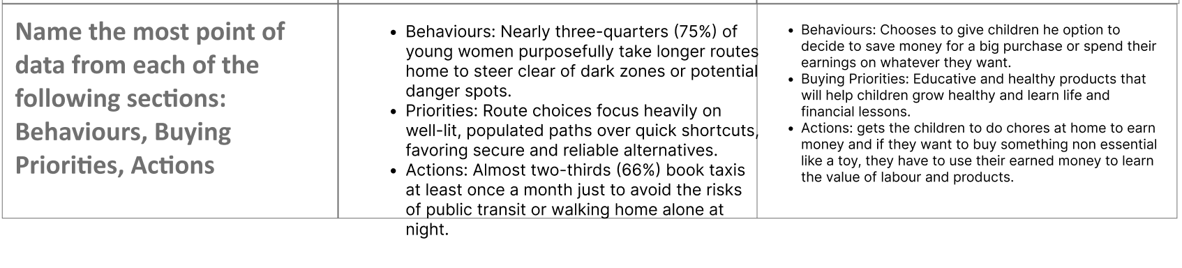
Consumer Trend Research

Personas Research
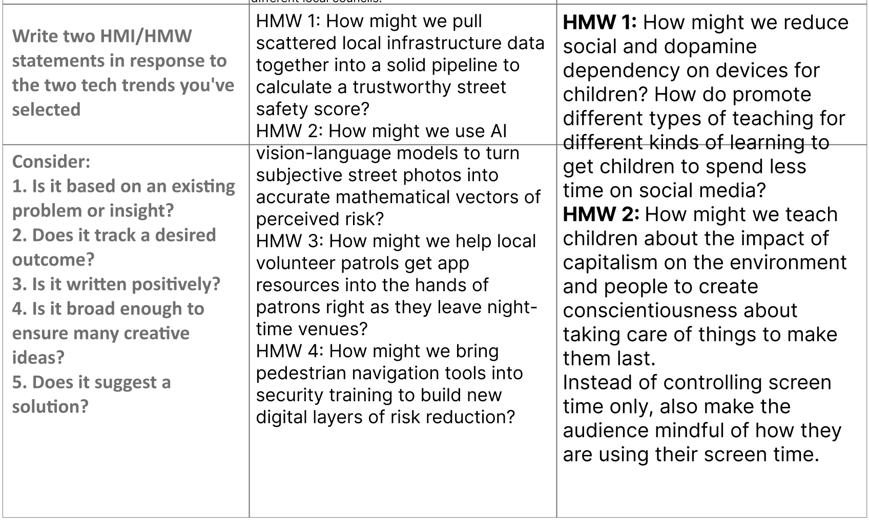
HMI Research

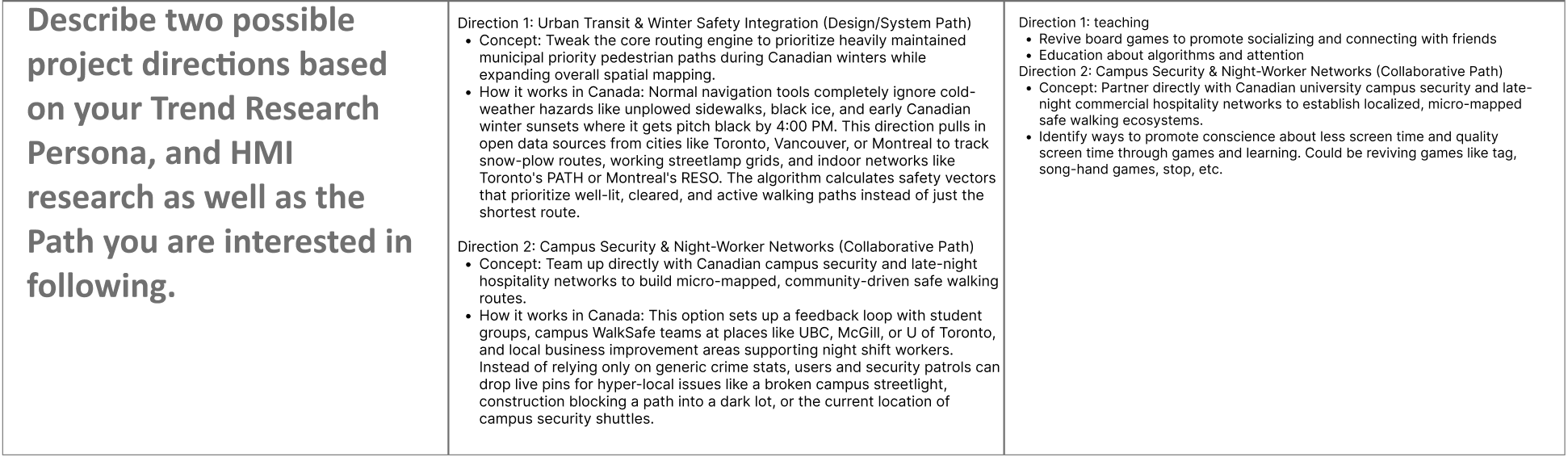
Project Path


Project 1 Concept


Project 1 Concept

Emergency Commuter Tool
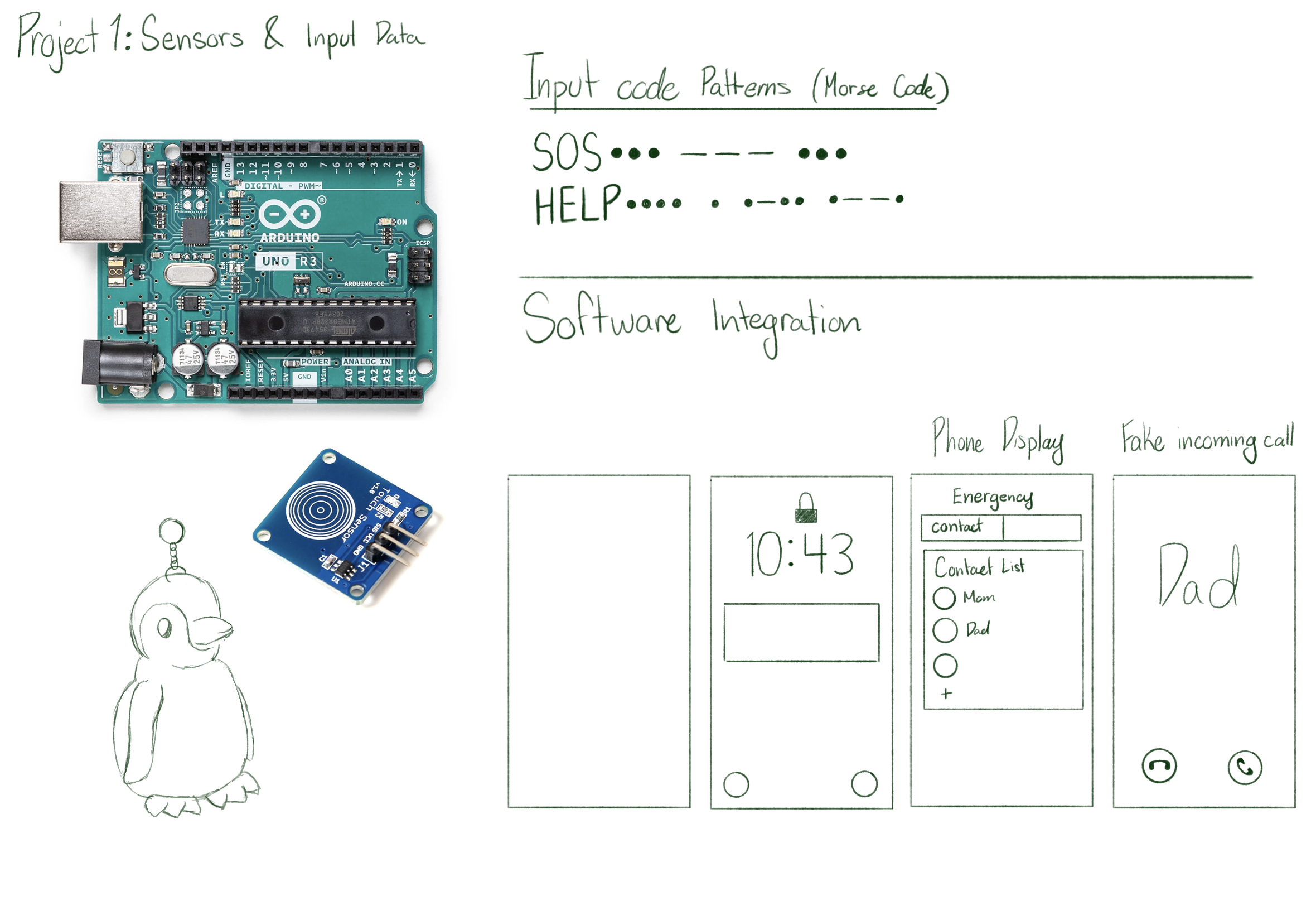
A stealth emergency notification system built into everyday wearables or keychain, allowing users to send silent alert codes without opening a phone.
×

Powered by w3.css